Gas Chromatography – How a Gas Chromatography Machine Works, How To Read a Chromatograph and GCxGC
Complete the form below to unlock access to ALL audio articles.
Contents
How does gas chromatography work?
Adding mass spectrometry to gas chromatography (GC-MS)
What is gas chromatography?
Gas chromatography (GC) is an analytical technique used to separate and detect the chemical components of a sample mixture to determine their presence or absence and/or quantities. These chemical components are usually organic molecules or gases. For GC to be successful in their analysis, these components need to be volatile, usually with a molecular weight below 1250 Da, and thermally stable so they don’t degrade in the GC system. GC is a widely used technique across most industries, including for:- Quality control in the manufacture of many products from cars,1 to chemicals and petrochemicals, to pharmaceuticals2
- Research purposes from the analysis of meteorites3 to natural products4
- Safety and monitoring from environmental samples, microplastics and food5-8 and wine, to forensics.9
Gas chromatographs are frequently hyphenated to mass spectrometers (GC-MS) to enable the identification of the chemical components.
How does gas chromatography work?
As the name implies, GC uses a carrier gas in the separation, this plays the part of the mobile phase (Figure 1 (1)). The carrier gas transports the sample molecules through the GC system, ideally without reacting with the sample or damaging the instrument components.
- The sample is first introduced into the gas chromatograph (GC), either with a syringe or transferred from an autosampler (Figure 1 (2)) that may also extract the chemical components from solid or liquid sample matrices. The sample is injected into the GC inlet (Figure 1 (3)) through a septum which enables the injection of the sample mixture without losing the mobile phase.
- Connected to the inlet is the analytical column (Figure 1 (4)), a long (10 – 150 m), narrow (0.1 – 0.53 mm internal diameter) fused silica or metal tube which contains the stationary phase coated on the inside walls.
- The analytical column is held in the column oven which is heated during the analysis to elute the less volatile components.
- The outlet of the column is inserted into the detector (Figure 1 (5)) which responds to the chemical components eluting from the column to produce a signal.
- The signal is recorded by the acquisition software on a computer to produce a chromatogram (Figure 1 (6)).

Figure 1: A simplified diagram of a gas chromatograph showing: (1) carrier gas, (2) autosampler, (3) inlet, (4) analytical column, (5) detector and (6) PC. Credit: Anthias Consulting.
After injection into the GC inlet, the chemical components of the sample mixture are first vaporized, if they aren’t already in the gas phase. For low concentration samples the whole vapour cloud is transferred into the analytical column by the carrier gas in what is known as splitless mode. For high concentration samples only a portion of the sample is transferred to the analytical column in split mode, the remainder is flushed from the system through the split line to prevent overloading of the analytical column.
Once in the analytical column, the sample components are separated by their different interactions with the stationary phase. Therefore, when selecting the type of column to use, the volatility and functional groups of the analytes should be considered to match them to the stationary phase. Liquid stationary phases mainly fall into two types: polyethylene glycol (PEG) or polydimethylsiloxane (PDMS) based, the latter with varying percentages of dimethyl, diphenyl or mid-polar functional groups, for example cyanopropylphenyl. Like separates like, therefore non-polar columns with dimethyl or a low percentage of diphenyl are good for separating non-polar analytes. Those molecules capable of π-π interactions can be separated on stationary phases containing phenyl groups. Those capable of hydrogen bonding, for example acids and alcohols, are best separated with PEG columns, unless they have undergone derivatization to make them less polar.
The final step is the detection of the analyte molecules when they elute from the column. There are many types of GC detectors, for example: those that respond to C-H bonds like the flame ionization detector (FID); those that respond to specific elements for example sulfur, nitrogen or phosphorus; and those that respond to specific properties of the molecule, like the ability to capture an electron, as is used with the electron capture detector (ECD).
Adding mass spectrometry to gas chromatography (GC-MS)
Mass spectrometry (MS) is an analytical technique that can be hyphenated to a GC and used instead of the GC detector. The neutral molecules elute from the analytical column and are ionized in the ion source to produce molecular ions which can degrade into fragment ions. The fragment and molecular ions are then separated in the mass analyzer by their mass:charge (m/z) ratio and are detected. Data from a GC-MS is three dimensional, providing mass spectra that can be used for identity confirmation, to identify unknown analytes and to determine structural and chemical properties of molecules, as well as the chromatogram that can be used for qualitative and quantitative analysis.
How do you read a chromatogram and what does it tell you?
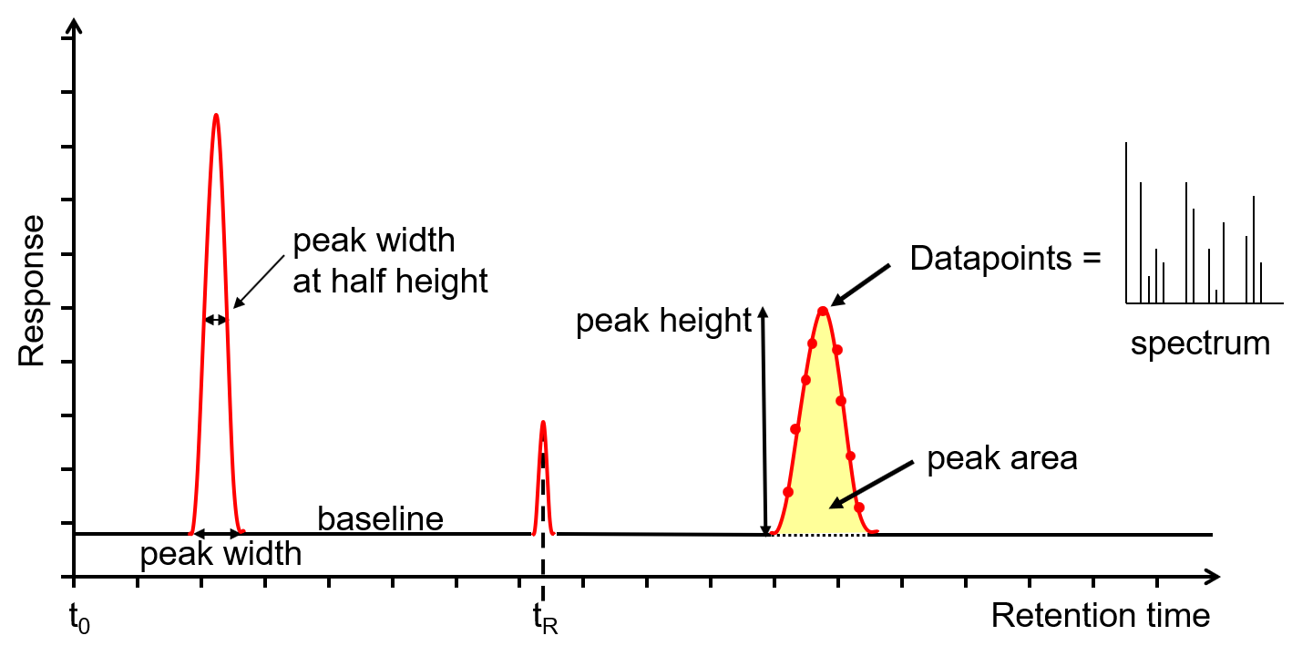
Figure 2: Chromatogram output from a GC or GC-MS. Credit: Anthias Consulting.
Much information can be gained from the chromatogram (Figure 2) on the health of the GC or GC-MS system as well as the data required to perform qualitative or quantitative analysis.
The x-axis is the retention time, taken from the time the sample was injected into the GC (t0) to the end of the GC run. Each analyte peak has a retention time measured from the apex of the peak, for example tR. The y-axis is the measured response of the analyte peak in the detector. The baseline shows the signal from the detector when no analyte is eluting from the column, or it is below the detection limit. The baseline response is a mix of electrical noise (usually low) and chemical noise, such as impurities in the carrier gas, column stationary phase bleed and system contamination. Hence, if the baseline is higher than it should be, it is an indication of a problem or that maintenance is required. Various measurements can be taken from the peak, such as width at the baseline, width at half height, total height and area. The latter two are proportional to the concentration, however it is the area that is used for quantitation as it is less affected by band broadening. The measurements can be used to calculate the extent of band broadening, the spread of the analyte molecules on the column. Narrower, sharper peaks give better sensitivity (signal to noise ratio) and better resolution (peak separation). The peaks shown are Gaussian, however peak tailing (the right side of the peak is wider) indicates activity or a dead volume in the system, whereas a peak fronting (the left side of the peak is wider) indicates the column is overloaded. Accurate measurements are affected by the number of data points across a peak, with an ideal number being 15-25. Too few, makes the peak look like a child’s join-the-dots drawing, affecting peak area, resolution and, with GC-MS, deconvolution. Too many reduces the signal to noise, reducing sensitivity. For GC-MS data, each data point is a mass spectrum, the third dimension of data.
Taking gas chromatography into multiple dimensions
Compared to some other separation techniques, GC has a high peak capacity with the ability to separate hundreds of compounds. However, for some applications where thousands of peaks need to be separated, there aren’t enough theoretical plates to chromatographically separate them all. Examples may include the analysis of diesel,10 or where trace analytes need to be detected in complex matrices like environmental, biological or food11 samples. Spectral resolution, where an MS is hyphenated to a GC, enables analysis to be performed without full chromatographic resolution, however the coeluting peaks must have different spectra for this to be fully successful.

Figure 3: Simplified diagram of GC x GC analysis. Credit: Anthias Consulting.
Heart-cutting is useful where a column is selected to separate the majority of the peaks, then a few groups of coeluting peaks are “cut” and transferred onto a second column containing a different stationary phase and selectivity (Figure 3). Only a few cuts can be transferred through the run, therefore it can only be used where there are a few problem separations.
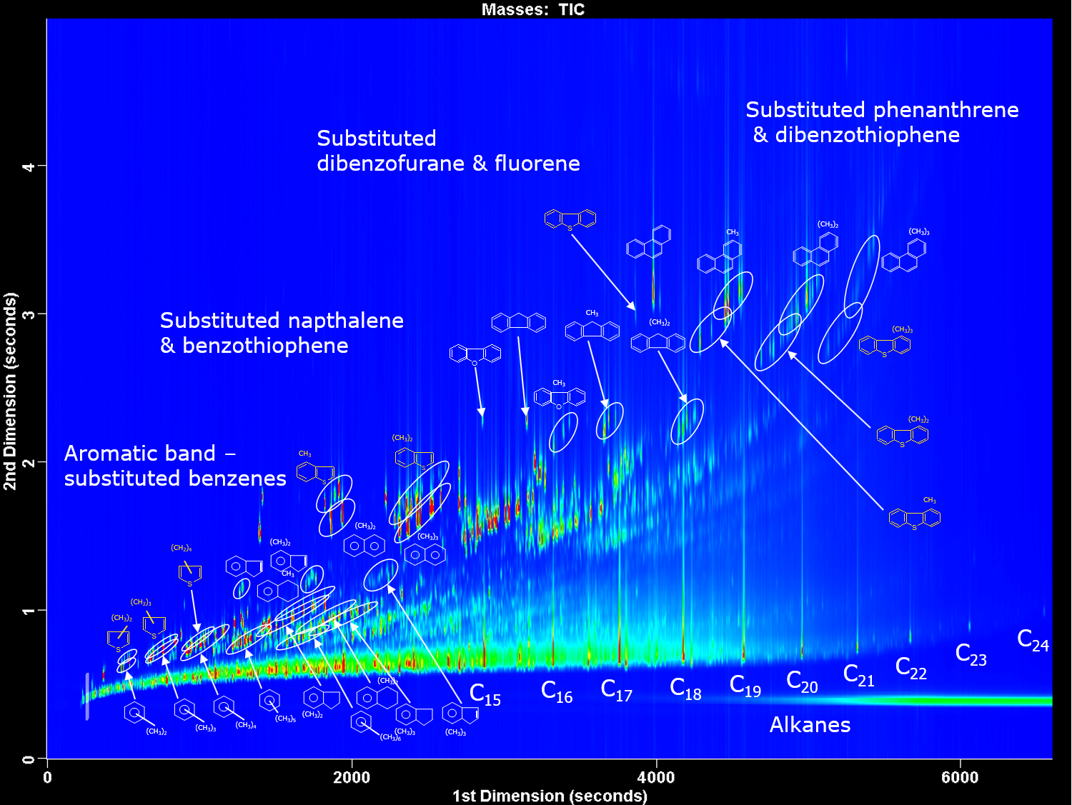
Figure 4: GC x GC contour plot of diesel showing the different chemical classes separated. 1st dimension column is non-polar and 2nd dimension column is mid-polar. Credit: Anthias Consulting.
For complex samples where there are frequent coelutions, comprehensive two-dimensional chromatography (GC x GC) is used. Two columns, containing different stationary phases and therefore different separation mechanisms, are set-up in series. The “normal” set-up is a 1st dimension non-polar column followed by a 2nd dimension more polar column, as shown in Figure 4, for the analysis of diesel. A modulator is used between the two columns to take a cut from the first column and reinject in a narrow sample band onto the second column. Thermal modulators achieve this using temperature to trap and then release the molecules, flow modulators collect the effluent, compress and flush the molecules onto the second column. Cuts are taken throughout the run, usually every 1 to 10 seconds. Separation on the second column should be achieved before the next cut is introduced. This fast separation is achieved by using a short, narrow second column, usually 1-2 m of 0.1 mm internal diameter used with thermal modulators; or a short, wider second column, usually 5 m of 0.25 mm internal diameter used with flow modulators. GC x GC peaks are very narrow, down to 35 ms, therefore fast GC detectors or high acquisition rate mass spectrometers >100 Hz must be used to acquire enough data points.
Strengths and limitations of gas chromatography
GC is a widely used technique across most industries. It is used for routine analysis through to research, analysing a few to many hundreds (or thousands with GC x GC) of compounds in many different matrices, from solids to gases. It is a robust technique and is easily hyphenated to other techniques including mass spectrometry.
GC is limited to analysing volatile compounds from helium/hydrogen up to molecular weights of around 1250 u. Thermally labile compounds can degrade in a hot GC, therefore cold injection techniques and low temperatures should be used to minimize this. More polar analytes can become stuck or lost in the GC, therefore the system should be deactivated and well-maintained or these analytes derivatized.
Common problems with gas chromatography
The most common problem in GC is leaks. The mobile phase is a gas and flows throughout the system, therefore the correct installation of parts and consumables is important along with regular leak checking.
Activity is another issue for more polar analytes, especially those at trace levels. Silanol groups on the glass liners and column, and also a build-up of dirt in the system can cause tailing peaks, irreversible adsorption or catalytic breakdown. The inlet is the area that causes most problems as it is here the sample is injected, vaporized and transferred into the GC column. Therefore, regular inlet maintenance along with using the correct consumables, for example a deactivated inlet liner, is important to keep the instrument trouble-free.
